
What happens when you turn on computer?
Ever wondered what happens when you press the power button on your computer? We will peek into how CPU, firmware, and bootloader work together before the OS takes over.

When you press the power button, it feels like your computer “just starts.” A few seconds later, the familiar login screen is there, ready for you. But under the hood, a fascinating sequence of steps takes place in microseconds, the CPU waking up at a fixed address, the firmware checking hardware, and the bootloader preparing the operating system. This post takes you through that invisible journey, from the very first jolt of electricity to the moment your OS begins to run.
Before we dive in, here’s a quick overview of the key steps that happen when you turn on your computer:
Power-On and Reset: The CPU starts in a known state.
Firmware Execution (BIOS/UEFI): Hardware checks and setup.
POST (Power-On Self Test): Basic hardware testing.
Boot Device Selection: Choosing where to load the OS from.
Bootloader Execution: Preparing the system for the OS.
Operating System Handoff: The OS takes control.
Now let’s dive deeper into each step, starting with what happens the moment you press the power button.
1. Power‑On & Hardware Reset
When you press the power button, the system doesn’t start executing instructions right away. First, the hardware needs to stabilize and the CPU must be placed in a known starting state. This stage prepares the machine before any firmware code can run.
1. Power‑Good Signal
The power supply stabilizes voltages and asserts a “Power‑Good” (PWR_OK) line to the motherboard. All devices receive power and begin to initialize themselves. The Central Processing Unit (CPU) is initially held in a reset mode, meaning it's not yet executing instructions. The memory layout is powered up, although the RAM itself has no content since it's volatile.
Once the system has stable power, the CPU is released from reset, but it needs to know where to start executing code.
2. CPU Reset Vector
The reset vector is a predetermined memory address where the CPU begins execution after being powered on or reset. On x86 processors, this address is typically 0xFFFFFFF0 (near the top of the 4GB address space). The motherboard’s memory mapping ensures that this address points to the BIOS/UEFI firmware ROM chip, so the very first instruction the CPU executes comes from the firmware.
Before executing those instructions, though, the CPU may need a bit of self-initialization.
3. Microcode / Internal Init
Microcode is low-level firmware that lives inside the CPU itself. It sits between the hardware and the instruction set architecture (ISA), implementing complex instructions as sequences of simpler operations. Modern CPUs may also load or patch microcode from firmware to work around hardware errata before running user-visible instructions.
2. Firmware Initialization
Once the CPU has a stable starting point, control passes to the system firmware (BIOS or UEFI) stored in non-volatile memory. The firmware’s job is to check the health of the system, bring hardware into a usable state, and prepare the environment for the bootloader.
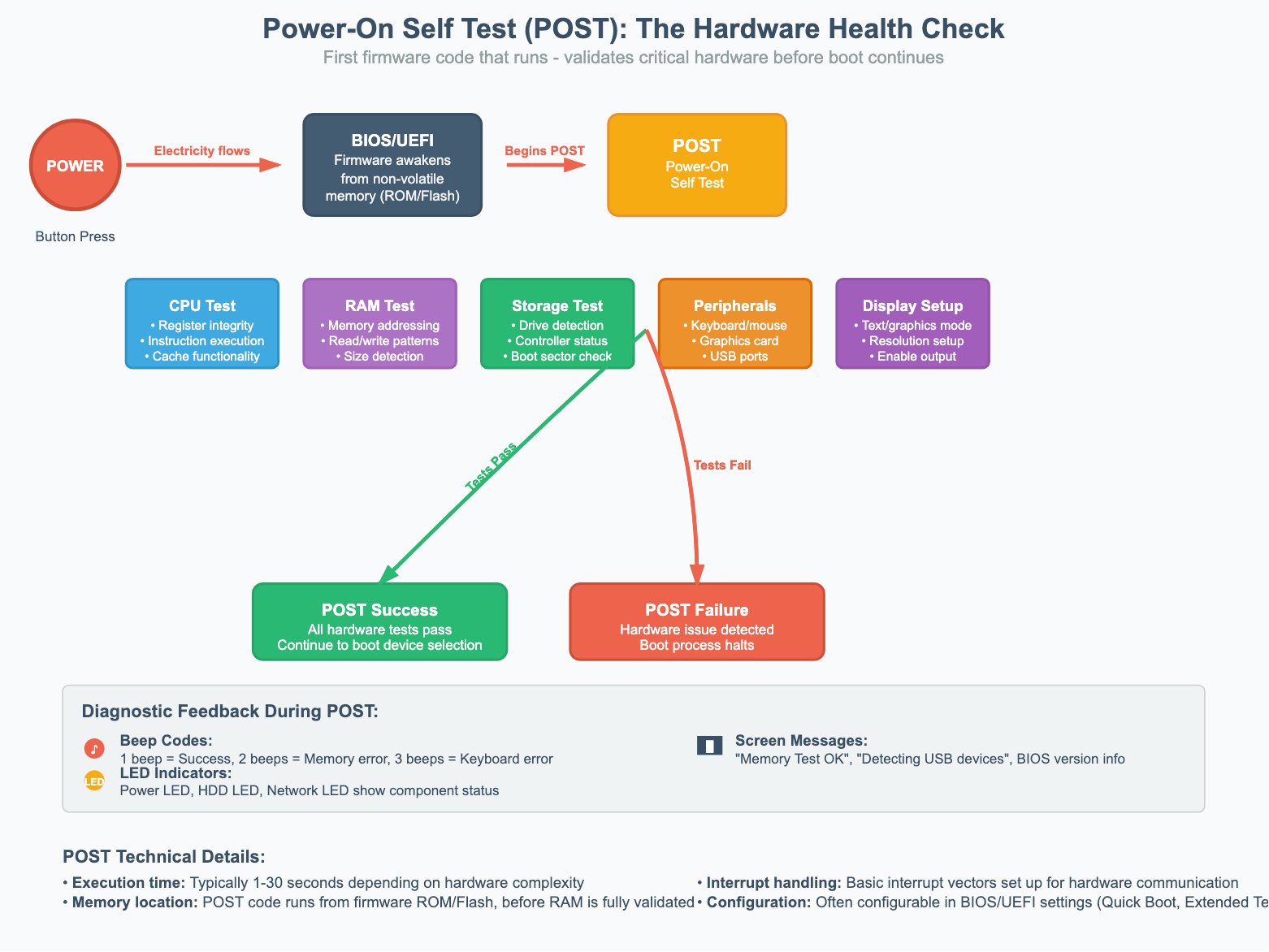
1. POST (Power-On Self Test)
The firmware begins with a diagnostic phase called POST. It checks essential components like RAM, CPU, storage devices, and peripheral connections. During this phase, you may hear beeps or see LED indicators, these are diagnostic codes that reveal whether hardware has passed or failed the tests. The firmware also sets up a basic text or graphics mode so you can see system messages.
Once the system passes POST, the firmware moves on to configuring the hardware in more detail.
2. Core Hardware Initialization
After POST, the firmware initializes hardware in a specific sequence. It configures the CPU, sets up memory controllers, initializes storage controllers, and establishes communication between components. It also detects and catalogs all connected hardware, building a resource map that will later be passed to the operating system.
But not all hardware is part of the motherboard itself — expansion cards may also need their own initialization.
3. Option ROMs & Plug-In Cards
The firmware scans PCI and PCIe slots for add-in cards that contain their own firmware, called Option ROMs. Think of these as mini-BIOS programs embedded on the card. Common examples include:
RAID controller cards: initialize disk arrays
Network interface cards (NICs): support PXE/network boot
Graphics cards: contain video BIOS to bring up the display
Storage controllers (SCSI/SAS): manage attached drives
When the firmware finds an Option ROM, it loads and executes it so the card can initialize itself and register its services. This ensures the operating system will see not just the motherboard hardware, but also any special capabilities provided by expansion cards.
3. Boot Device Selection
With the hardware initialized, the firmware now needs to decide where to load the next stage of software from. This step determines which storage device (or even network location) becomes the source of the bootloader.
1. Boot Order
The firmware follows a boot priority list (which you can configure in BIOS/UEFI settings). It checks devices like hard drives, SSDs, USB drives, optical discs, or network boot sources in sequence.
On legacy BIOS systems, it looks for a special boot signature
0x55AAat the end of the first sector.On UEFI systems, it looks inside the EFI System Partition for a valid EFI boot application.
If a device fails to respond or has no bootable code, the firmware moves on to the next one in the list. If none succeed, you’ll see an error like “No bootable device found.”
Once a valid boot device is found, the firmware must ensure that what it’s about to load is safe.
2. Secure Boot (UEFI only)
On modern UEFI systems, Secure Boot adds a layer of protection by creating a cryptographic chain of trust. The firmware contains a database of trusted keys, and it will only load bootloaders or kernels that are signed by these keys. This prevents rootkits, malicious loaders, or unauthorized operating systems from sneaking into the boot process.
4. Bootloader Stage: MBR vs GPT
Once the firmware has chosen a boot device, the next question is: how is the disk organized, and where does the first code live?
For decades, the answer was the Master Boot Record (MBR). Modern systems, however, mostly use the more powerful GUID Partition Table (GPT). Let’s walk through both.
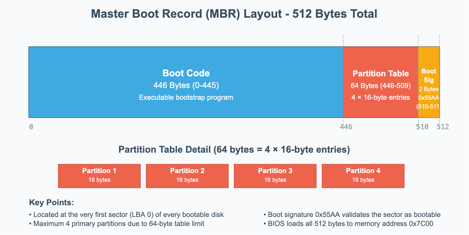
Master Boot Record (MBR) — Legacy BIOS Systems
The MBR lives in the very first sector of a disk (LBA 0). It’s just 512 bytes, but it contains two critical things:
A small piece of executable boot code.
The partition table for the disk (up to four entries).
Note: Think of LBA as a simple numbering system that starts from 0 and counts up sequentially. Modern storage devices use LBA as an abstraction layer that hides the physical complexity of how data is actually stored. Whether it's a traditional hard drive with physical cylinders, heads, and sectors, or a solid-state drive with flash memory cells arranged in pages and blocks, the operating system and firmware see everything as a linear sequence of logical blocks.
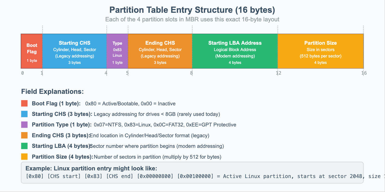
Partition Table Format in MBR
MBR’s partition table can contain up to 4 partition table entries with the below format.
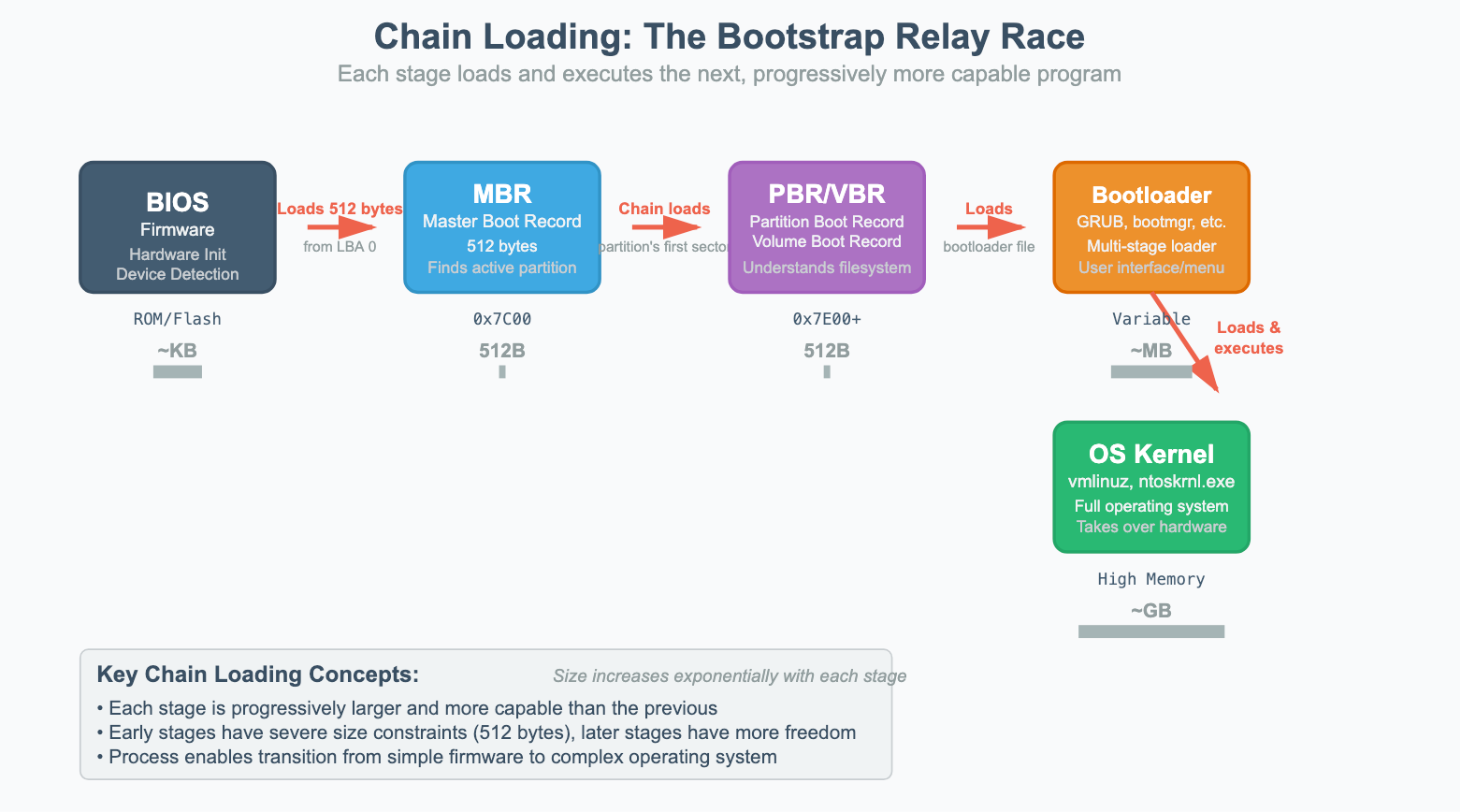
How the BIOS uses MBR?
BIOS loads the 512-byte MBR into memory at address
0x7C00and jumps into that code.The code checks the partition table, finds the one marked “active,”
and loads that partition’s first sector (the Partition Boot Record).
From there, the OS’s actual bootloader (like GRUB or Windows Bootmgr) takes over.
Limitations of MBR
Only 4 primary partitions (hack: extended partitions with logical drives).
Max disk size: 2 TB (due to 32-bit addressing).
No redundancy: if the MBR is corrupted, the whole disk fails to boot.
That’s why workarounds like extended partitions became necessary. One partition could act as a container for multiple “logical” partitions.
A common disk layout might look like this:
Primary Partition 1: Windows OS (C:)
Primary Partition 2: Linux OS
Primary Partition 3 (Extended Partition Container):
Logical Partition 1: Data Drive (D:)
Logical Partition 2: Backup Drive (E:)
Logical Partition 3: Shared Files (F:)
Primary Partition 4: Empty/Unused
This system was a functional, if complex, workaround. However, it's a perfect example of the legacy baggage that led to the development of the much simpler and more powerful GUID Partition Table (GPT).
GUID Partition Table (GPT) - Modern UEFI Systems
GPT is a much more sophisticated partitioning scheme that addresses all of MBR's limitations. It's part of the UEFI specification and provides better data integrity and flexibility.
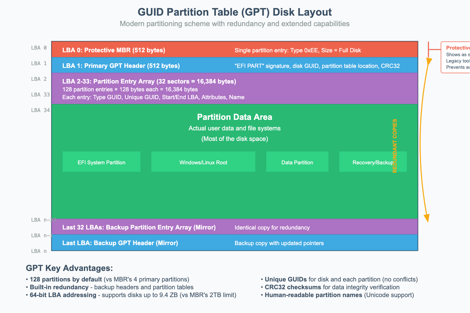
GPT Disk Layout Strcture
LBA 0: Protective MBR: For backward compatibility, the very first sector of a GPT disk still contains a 512 byte MBR styled memory called "protective" MBR. This MBR has a single partition entry of size same as disk's size and type
0xEE(invalid partition type, to prevent legacy tools from misidentifying). This tricks the legacy MBR-only tools into thinking that the disk is already full so it can't create any new partitions from misidentifying the disk as unformatted and accidentally overwriting it.LBA 1: Primary GPT Header: This header defines the layout of the partition table itself. It contains:
A signature ("EFI PART") to identify it as a GPT disk.
The location of the partition entries.
The number of partition entries.
A unique GUID (Globally Unique Identifier) for the entire disk.
A CRC32 checksum for the header and the partition table, which allows the system to verify their integrity.
LBA 2 to LBA 33 (typically Partition Entry Array): This is where the actual partition information is stored. By default, GPT allocates space for 128 partition entries (128 bytes each), though this can be changed.
Partition Data: The rest of the disk is used for the actual partitions.
Last 33 LBAs: Backup GPT header and partition entries (mirror of the beginning).
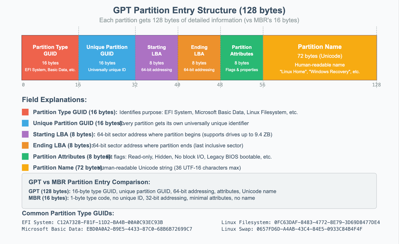
GPT Partition Entry Structure
GPT/UEFI Boot Process:
The boot process on a UEFI system with a GPT disk is fundamentally different and more robust than the legacy BIOS/MBR method.
The UEFI firmware initializes and scans the storage devices.
Instead of executing code from a boot sector, the UEFI firmware actively looks for a specific partition known as the EFI System Partition (ESP). The ESP is identified by its Partition Type GUID.
The UEFI firmware understands file systems (typically FAT32), so it can mount the ESP and browse its contents.
It looks for a bootloader application at a standardized file path, such as
\EFI\BOOT\BOOTX64.EFI(for removable media) or a vendor-specific path like\EFI\Microsoft\Boot\bootmgfw.efifor Windows.Once found, the firmware executes this
.efibootloader file directly, which then takes over to load the operating system kernel.
5. Kernel Loading
Once the bootloader has been identified and executed by the BIOS/MBR or UEFI/GPT process, it takes on a single responsibility: find the operating system’s kernel, load it into memory, and hand over control. This is the turning point where the operating system itself begins to take charge.
1. Bootloader to Kernel Handoff
Bootloaders like GRUB (Linux) or the Windows Boot Manager know exactly where to find the kernel file on disk (vmlinuz for Linux, ntoskrnl.exe for Windows ). But the kernel by itself isn’t enough to start running.
Modern kernels are modular: they don’t carry every possible hardware driver built-in. This creates a chicken-and-egg problem — the kernel needs drivers to access the storage device, but those drivers are stored on the storage device.
To solve this, the bootloader also loads an initial RAM disk (initrd) or initial RAM filesystem (initramfs) into memory alongside the kernel. This is a temporary, compressed filesystem that contains just enough drivers and tools for the kernel to mount the real root filesystem and continue booting.
2. Preparing the Environment
Before transferring control, the bootloader must carefully prepare both memory and CPU state so the kernel can run smoothly.
Memory Layout:
Places the kernel at a safe memory address (around 1MB on x86 systems).
Creates a memory map so the kernel knows which areas are free or reserved.
Sets up initial page tables for virtual memory management.
Preserves important boot information (like initrd location) in memory.
CPU State:
Switches the CPU out of 16-bit real mode into 32-bit protected mode or 64-bit long mode.
Disables interrupts temporarily to prevent unexpected events.
Initializes the stack pointer and CPU registers with clean values.
Loads boot parameters that the kernel will consume next.
3. Boot Parameters
These boot parameters are essential hints passed from the bootloader to the kernel. Examples include:
Linux: Kernel command line arguments, initrd location, memory map.
Windows: Boot Configuration Data (BCD) and hardware abstraction details.
ARM systems: Device Tree (DTB) describing available hardware components.
4. Control Transfer
With the kernel in place, drivers loaded from initrd, memory mapped, and CPU state initialized, the bootloader has done its job. It jumps to the kernel’s entry point and hands over control entirely. From this moment onward, the operating system kernel is in charge.
6. Kernel Initialization: Building the System
The moment the kernel begins executing, it runs in a highly constrained environment. It must bootstrap itself, initializing all its core subsystems to transform the raw hardware into a fully functional operating system.
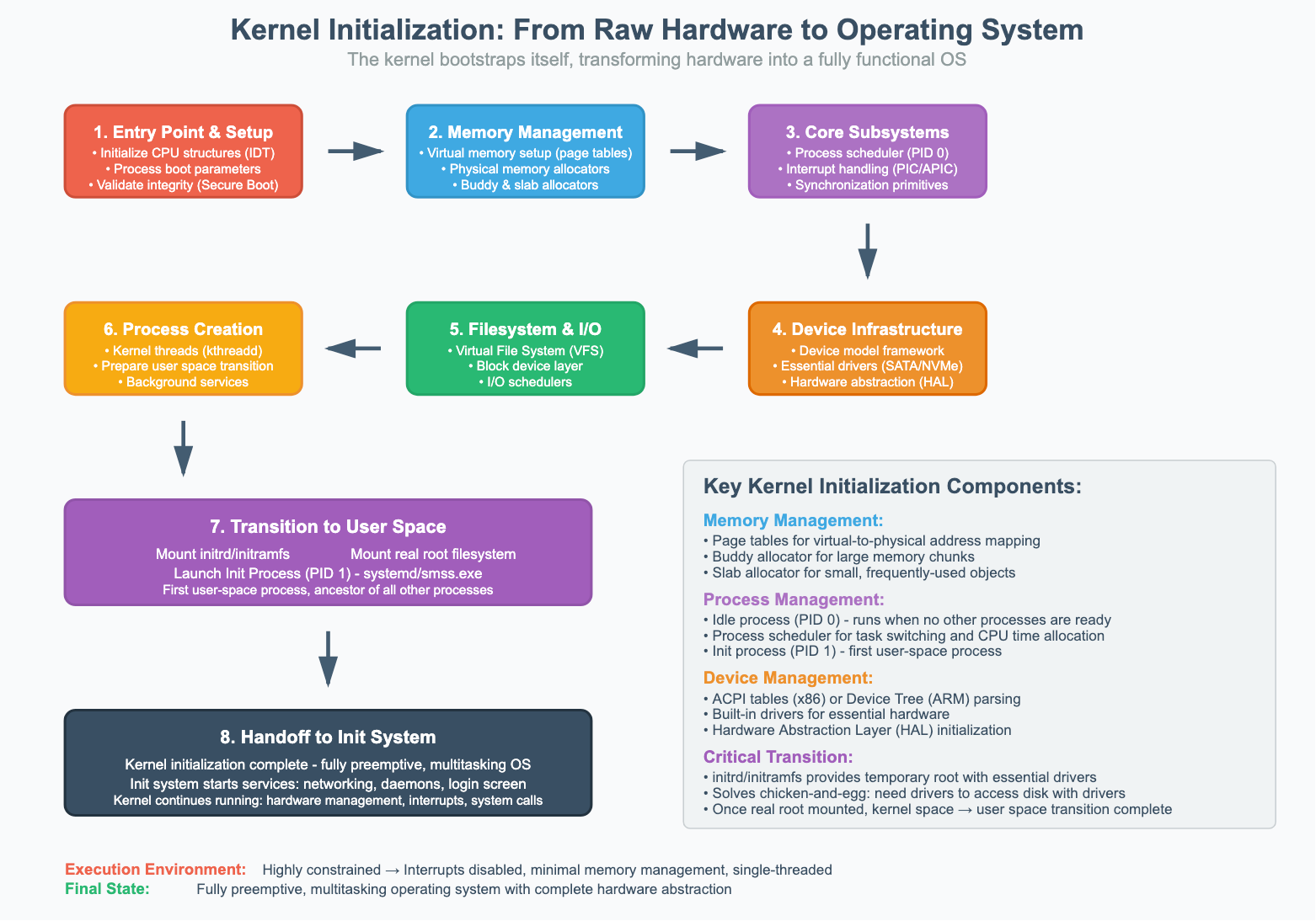
1. Entry Point and Early Setup
The kernel’s very first instructions are architecture-specific and focus on creating a stable environment for the rest of the initialization:
Initializes Core CPU Structures: Sets up the Interrupt Descriptor Table (IDT) to handle hardware interrupts and exceptions, though interrupts remain disabled for now.
Processes Boot Information: Parses the command-line arguments and memory map passed by the bootloader to understand its environment and available resources.
Validates Integrity: If Secure Boot is enabled, the kernel validates its own digital signature to ensure it hasn’t been tampered with.
2. Memory Management Initialization
The kernel immediately takes control of all system memory:
Virtual Memory Setup: It creates a comprehensive set of page tables to map virtual addresses to physical RAM addresses, establishing the kernel’s own protected address space.
Physical Memory Management: Using the map from the bootloader, it builds a complete picture of physical memory, initializing allocators (like the buddy and slab allocators) to manage free and used memory frames.
3. Core Subsystem Initialization
With memory management active, the kernel brings its fundamental components online:
Process Management: Creates the first process, the idle process (PID 0), and initializes the process scheduler, which is responsible for task switching.
Interrupt and Exception Handling: Configures the system’s interrupt controllers (PIC/APIC) and enables interrupts, allowing hardware to communicate with the CPU.
Synchronization Primitives: Initializes the low-level mechanisms like mutexes, semaphores, and spinlocks that are essential for preventing data corruption on multiprocessor systems.
4. Device and Driver Infrastructure
The kernel sets up the framework for communicating with hardware:
Device Model Framework: Initializes the device driver subsystem and parses hardware information from ACPI tables (on x86) or a device tree (on ARM) to discover what hardware is present.
Essential Driver Loading: Loads the built-in drivers compiled directly into the kernel, focusing on those needed to access the root filesystem (e.g., SATA/NVMe drivers).
Hardware Abstraction: Initializes platform-specific code and Hardware Abstraction Layers (HAL) to provide a consistent interface for the rest of the kernel to interact with the underlying hardware.
5. Filesystem and I/O Preparation
Before it can mount the root filesystem, the kernel prepares its I/O subsystems:
Virtual File System (VFS): Initializes the VFS, an abstraction layer that allows the kernel to treat all filesystems (like ext4, NTFS, etc.) in a uniform way.
Block Device Layer: Initializes the subsystem that manages block devices (like hard drives and SSDs) and sets up I/O schedulers to optimize disk requests.
6. Initial Process Creation
The kernel creates its own essential background threads (like kthreadd for managing other kernel threads) and then prepares to make the critical leap from kernel space to user space.
7. Transition to User Space
Mounting the Root Filesystem: The kernel first mounts the initrd/initramfs as a temporary root filesystem. The drivers and tools in the initrd are used to mount the real root filesystem from the main storage device.
Launching the Init Process: The kernel creates the very first user-space process, which is given Process ID 1 (PID 1). This process is the ancestor of all other user processes. On modern Linux systems, this is systemd; on Windows, it’s smss.exe.
8. Handoff to the Init System
At this point, the kernel’s primary initialization is complete. It has transformed into a fully preemptive, multitasking operating system kernel. While the kernel continues to run for the lifetime of the system—managing hardware, handling interrupts, and processing system calls—it now hands the responsibility of finishing the boot process to the init system. The init system is responsible for starting all the higher-level services, such as networking, background daemons, and ultimately, the user login screen.